Plume-Surface Interactions for the Moon and Mars
Beta Prototype
Overview
The beta prototype was designed based upon the outcomes and observations of the final alpha prototype. Various components were either updated or re-designed altogether, and the various subsystems of the experimental setup were tested separately before being incorporated together into the final physical model. At the conclusion of this phase of the project, the team had a functional beta prototype ready for further testing, both at ambient conditions and at vacuum conditions in the shock tunnel.
Component Modifications and Improvements
Some key structural components of the alpha prototype was changed in order to accommodate the changes in the electromechanical system, as well as the limited space and viewing angles inside the hypersonic shock tunnel test section. Originally, the assembly included two nearly identical square plates. One connected to the impingement plate, and the other connected to the electromechanical system in order to lift the impingement plate. These plates were then fastened together. However, it was quickly determined that having two of these plates was redundant and only added unnecessary weight for the motor to overcome. Instead, one
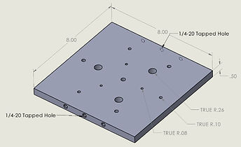
Re-Machined Square Plate.
plate was re-machined to serve both roles as the mounting point of the impingement plate and the connection to the electromechanical system. This also served to provide a better view of the impingement plate within the tunnel by decreasing the maximum height of the model.
As previously mentioned, the original linear actuator used was too big for the shock tunnel test section. This led to the team's decision to use the stepper motor purchased earlier in the fall. For the electromechanical system to work without physical interference, a new part needed to be designed to allow the impingement plate to translate up and down along the stepper motor's lead screw. This decision was made was in conjunction with the decision to replace the double-square-plate situation with a single re-machined square plate. The location of the holes on the new plate influenced the design of the new connector piece that was modeled.
There were three main design factors that had to be considered. First, the connection holes needed to line up with the plate holes. Secondly, there had to be a cavity within the new part to allow the stepper motor's lead screw to travel inside of it. Thirdly, the bottom of the new part had to be compatible with the brass nut that came with the stepper motor. The final design created and 3D printed is shown here in blue.
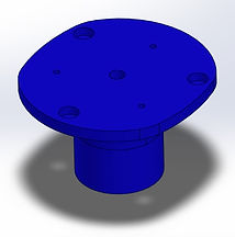


Stepper Motor Plate Attachment - 3D Model (left), Inside View (center), Assembled to Plate (right).
Another component that underwent changes moving into the final beta prototype was the t-post design. The t-posts were created to support the impingement plate (the top-most round, flat plate supporting sensors). These posts hold the plate in

place as it undergoes the force of the impinging jet in the tunnel, as well as allowing the plate to rotate about its center axis to accommodate different impingement angles. These posts were 3D printed for the alpha prototype, but they were relatively weak in comparison to the weight of the plate, showing signs of light wear over time. The original t-post design also did not account for the need to hold the angle adjustment pin in place during testing so that the plate does not move or fall. The new t-posts printed, shown in the image here, have greater reinforcements and structural integrity overall, as well as built-in notches in which the angle adjustment pin can rest so as not to move unnecessarily.
Re-Designed T-Post.
Similarly, the angle adjuster also underwent design changes from the alpha prototype model. The original angle adjuster, 3D printed in white as seen in previous photos, served its purpose but was not as structurally sound. A second version was printed with structural supports on each side of the semicircle pieces, but the overall dimensions of the adjuster were decreased too much and it was no longer efficient when trying to adjust the angle as part of the whole setup. The holes were also miscalculated and it was unable to be properly attached to the impingement plate. The third version, pictured here and 3D printed in black, was modeled similarly to the original angle adjuster with larger hole spacing and a larger base. This third version also had properly aligned holes for attachment and the new structural support design of the second model, scaled up to fit the new piece.

Re-Designed Angle Adjuster.
A new addition to the overall design incorporated in the beta prototype is the limit switch. This switch is tasked with stopping the downward motion of the actuator when pressed so that the setup cannot descent farther than necessary. If the plate proceeds too far down the stepper motor's lead screw, it will require manual resetting, so it is important to ensure the plate stays within a certain height range while it moved up and down. In order for the switch to accomplish this task, it required a new component to be designed. The final limit switch holder shown here was 3D printed in order to hold the limit switch up at a certain height, with a hollow center to allow for wired connections to the switch. In practice, as the plate is actuated down, it eventually presses the switch, stopping the plate until the next command is executed.

Limit Switch Holder.
Finally, a top priority part to be re-machined was the tunnel mount, the bottom plate serving as both the connection to the shock tunnel test section and the base of the entire experimental setup. This part must be capable of securely mounting to the existing holes of the test section without interfering with the current projects that are in the test section. In addition, this part must allow for the stepper motor of the electromechanical system to be mounted securely. This part was anticipated to be the hardest to produce

Tunnel Mounting Plate.
because of the many constraints surrounding it. A 3D model of the final tunnel mount plate is shown here, with new holes drilled for mounting the stepper motor securely to the plate.
Electrical & Solenoid Subsystems
An updated schematic of the electrical wiring is shown here. Because the stepper motor does not have a potentiometer built in, unlike the original linear actuator chosen, new sensors were implemented for greater control. The beta prototype utilizes the fact that the stepper motor operates in discrete steps. The exact position of the end effector is not measured throughout the tests performed. Instead, the motor retracts until it reaches its "zero position", at which point the limit switch is pressed, providing a reference point for the position of the end effector. After touching this reference point, the Arduino calculates the number of steps required to move the end effector to the desired position. As a means of checking the position being tested, the stepper motor moves back to the reference position, counting the steps required to reach the reference as a means of position verification. Both the Arduino and the stepper motor are powered by an external 10V, 1.5A voltage/current-limiting power supply. When the test is ready to begin, the channel flagged "RELAY" receives 5V, turning on the relay of the electro pneumatic system and beginning the recording of the oscilloscope and Schlieren camera.

Electrical Subsystem Schematic.
Shown below is the electrical schematic used to control the sonic jet. The primary gas line is electrically opened and closed using a solenoid, however, because the team expects to perform tests using a variety of pressures, a stronger solenoid is required. The solenoid chosen requires power from an American outlet (120V, 60Hz AC). In order to meet these power requirements, as well as maintain centralized control from the Arduino, a relay was implemented. Using the relay, the high voltage AC signal can be controlled using a low current, 5V signal.

Solenoid Subsystem Schematic.
Subsystem Integration & Final Assembly
While the team is prepared for any complications that may arise during the actual testing phase of this project, the beta prototype in its current state stands ready to perform as needed in the test section. The electrical and solenoid subsystems have been integrated into the physical model, and each of the above mentioned components is machined, printed, and assembled together appropriately. The final assembly shown here, minus the limit switch and its housing, allows for both vertical motion and angle adjustment of the top impingement plate, as was required at the very start of this project.

Fully Assembled Beta Prototype.