Plume-Surface Interactions for the Moon and Mars
Experimental Setup & Testing
Overview
After many months of hard work and preparation, the team was finally allowed access to space within the Stevens Hypersonic Shock Tunnel to begin testing and data collection. Due to unforeseen additional constraints within the test section of the tunnel and new limitations on the space available, the final beta prototype's design was further adjusted to accommodate the lack of space and to ensure reliable data could still be collected in a timely manner.
Experimental Setup Model - Redesigned
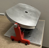
Due to the additional constraints placed on the space available, the final beta prototype (shown to the right here) was deemed too large, both in height and in base width. The model was not able to sit properly in the tunnel in order to reach the appropriate field of view for Schlieren imaging, and was too tall to have any height or angle adjustment capabilities. To accommodate for these issues, the beta model was broken apart into its subsections and some parts were reassigned.
The top impingement plate and angle adjuster assembly remained the same, but instead of being mounted to the stepper motor, this assembly was instead mounted upside down from the top surface of the tunnel's interior wall. The pressure sensor was therefore faced

Final Beta Prototype.
downward toward the base of the tunnel. This allowed enough space for the angle adjustment system to operate, while maintaining the plate surface and jet flow within the appropriate field of view. The impingement plate was also trimmed to ensure it would not come into contact with other testing apparatus within the tunnel. Because the plate was no longer to be actuated up and down, the nozzle itself was incorporated onto the stepper motor to create the desired height variation during testing. The nozzle and motor were mounted to the bottom floor of the tunnel so that the nozzle could actuate up and down towards the plate at its various angles during testing. This system was similar to one of the design concepts proposed and eventually eliminated during Phase I of this project.


Impingement Plate Assembly.
Nozzle and Motor Assembly.
Setup Mounted in Tunnel.
Setup in SolidWorks Tunnel Model.
The electrical system designed for the beta model remained largely the same since the same motor and pneumatic system were implemented overall. The pneumatic system design is shown in the schematic below.

Pneumatic System Schematic.

Solenoid and Regulator Setup.