Plume-Surface Interactions for the Moon and Mars
Alpha Prototype
Overview
The alpha prototype as it is described here is the product of the research, concept generation, and comparisons done previously. Because the proposed model consists of multiple subsystems, several preliminary alpha prototypes were created to demonstrate the functionality of each subsystem individually before combining everything into one design. The alpha prototype consists of a linear actuator equipped with a built-in potentiometer, driven by an L298 H-bridge motor controller. This controller is connected to an Arduino, which in turn is connected to a computer. When first turning on the Arduino, it establishes a serial communication with the computer. When prompted, it begins calibrating, moving the end effector to the furthest position and then to the closest position. This is done to determine the minimum and maximum potentiometer readings. Because these potentiometer readings are subject to inconsistencies in the signal, as well as imperfections in the wires and circuitry, base measurements are taken to account for any potential errors in the physical system. The user is then prompted to enter a distance in thousandths of an inch. After the request is completed, the linear actuator moves to the desired position, and then enters a braking mode. For consistency purposes, the measurement is then reported back to the user so that the user is aware of any distance errors. While the measurement of the position of the end effector has been proven to be accurate to one hundredth of an inch, the distance actually traveled is consistently shorter than the desired distance. This does not present a major problem because the user is still made aware of the actual distance, therefore limiting any inconsistencies when validating CFD models.
Subsystem Design and Testing
The first subsystem prototype was developed to demonstrate the proposed electromechanical design. The primary goal of this prototype was to showcase the design's ability to precisely and accurately control the position of the end effector with the given motor. By doing so, it could be ensured that the height and angle of the plate could be reliably controlled. Since the linear actuator had a built-in potentiometer and limit switches, closed loop control was easily implemented. In real time, the actuator was able to move, while receiving feedback on the current position of the end effector. It quickly became apparent that the potentiometer gave different values while the motor was on and while it was off. This was determined after a series of tests ensuring a constant input voltage was provided to the potentiometer, despite clear changes in current draw. To accommodate this, potentiometer readings were given to convey the final position to the user after the motor had been shut off. During this test run, the desired end effector height was unable to be produced. However, the height measured from the potentiometer matched the actual height within 1% error. Since the goal of the project is to produce empirical data to validate computational programs, as well as to provide insight into the fluid mechanics present, control of variables is significantly less important than the accuracy of measurements. In other words, the actual height of the end effector is less important so long as it is measured accurately.
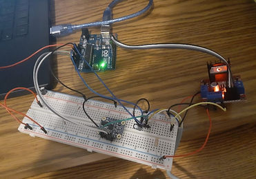
Electromechanical Subsystem Alpha Prototype.
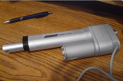
Linear Actuator.
While the results of testing the accuracy of control for the electromechanical subsystem were overall satisfactory, the system was ultimately too large to fit into the test section. The linear actuator was simply too large for practical use. Had this system been implemented into the final design, Schlieren imaging of the impinged flow would have been impossible. Instead, the electromechanical subsystem required redesigning in order to incorporate smaller actuators to meet the length requirements.
In addition to the accuracy of the linear actuator, the accuracy of the absolute orientation IMU sensor was tested. Shortly after beginning testing, the IMU began to experience noticeable drift. In axes of rotation perpendicular to the direction of gravity, variability of up to 3 degrees was observed within the first minute of testing. Because of this, the sensor was deemed unsuitable for measuring the angle of the plate. However, the removal of this sensor does not propose any problems because of the discrete nature of the physical angle adjustment system.
Angle Adjustement Design Inspiration.

Another subsystem focused on mechanically changing the angle of the plate and accommodating the Piezotronics pressure sensor. Using the different aluminum plates that the team received from last year’s project group, as well as the various 3D printers available on campus, the team developed a method to manually adjust the main impingement plate’s angle. The design drew initial inspiration from standard gym bench equipment, much like that pictured to the right. This adjustment system uses a machined piece containing many holes, each of which corresponds to a specific angle dependent upon the user's desired bench setup. The user pulls out a pin, adjusts the bench angle to their preference, and then reinserts the pin into their desired angle’s hole, holding the bench in that position. This setup is a simple yet effective way to change the angle of the setup, which naturally appealed to the needs of this project.
The same methodology was used when designing the main angle adjustment piece that attached to the impingement plate. Given that the desired angle range for measurements was between 20°-70°, the holes on the piece were assigned in order to allow the plate to rotate from its original 90° orientation to 67.5°, 45°, and 22.5°. The part also included 3 mounting holes to line up with the already existing 0.25-20 screw holes on the plate, and a circular cutout was made in the center of the part to account for the pressure sensor connection and wiring.

Original Angle Adjuster Design.
In order to hold the plate in place at a given angle, small L-brackets were modeled and 3D printed to restrict the pin from moving side to side, as well as T-shaped posts to hold the impingement plate up. Additionally, in order to accommodate these new parts, the aluminum plates from last
year’s project required machining. This involved drilling two sets of three 0.25-20 holes to allow the T-shaped pieces to screw into the bottom square plate, as well as two threadless holes on the impingement plate that allowed for rotation and also served as a connection to the T-shaped pieces. A SolidWorks drawing of these initially combined components, including the original angle adjuster, L-brackets, T-posts, and impingement plate is shown below.

Angle Adjustment Assembly.
Because adding pressure sensors to the plate was one of the group’s most important goals, the most significant machining done was the drilling of the hole for the Piezotronics pressure sensor in the middle of the impingement plate. A visual of the hole used to secure the sensor, as well as a schematic of the available sensor's dimensions, is provided below.

Pressure Sensor Hole in Impingement Plate (left) and Sensor Schematics (right).
While this design was able to accommodate the angle range outlined by the team's advisors, it had a few limitations and drawbacks that the team intended to improve upon in the next phase of the project. Although it remains untested in the shock tunnel test section, one main point of concern was how well the design would handle vibrations. Excessive vibrations within the apparatus leads to interference with the Schlieren imaging and overall data acquisition. Additionally, the team needed to test and decide if more actuators were needed to provide the plate with more stability and vibration reduction, despite the fact that one actuator alone has enough thrust capability to lift the entire system.
Another concern was that any 3D-printed parts printed with partial infill, such as the pin brackets, may fail due to rapid expansion from the sudden pressure increase in the chamber during testing. This concern was alleviated by the advice of the team's advisors and other lab members who had no trouble with 3D-printed parts in the past, specifically in use within the shock tunnel. In the event that the team's printed parts are inadequate as testing progresses, they are prepared to solve the issue by machining any necessary parts. The most likely to require machining would be the T-posts and pin bracket pieces as they are smaller and less structurally stable overall. These could be made from aluminum or stainless steal, although steel would be ideal to prevent any bonding to the impingement plate over time. Another way to improve these parts specifically could be to add additional channels and brackets in order to stabilize the pin holding the plate at an angle. Ideally, the angle would be remotely adjustable in the future, but for the time being and in the interest of making timely progress, the team is focusing on creating a reliable adjustment method before concerning themselves with the automation aspect. One option for this to be explored down the road is to replace each side of the 3D-printed angle adjustment piece containing the angle holes, with gears that would interact with a motor gear system on the square base plate immediately below it.
Preliminary Ambient Testing
The pressure transducer was integrated into the physical system and the first series of ambient tests were conducted to test the data acquisition method and the pressure sensor functionality. In these tests, the transducer was connected to a signal

conditioner, which was then connected to an oscilloscope to measure and record the changes in voltage given by the sensor. For ambient testing, the transducer was sprayed with refrigerant from a “can of compressed air” commonly used to remove dust from computers. The recording was triggered when the sensor gave a reading surpassing the threshold voltage. While the data was primarily exported as a .csv file, a screenshot of the graph generated by the first ambient test is shown to the right.
Raw Signal - Ambient Test 001.
The graph depicts a number of system characteristics. First and foremost, it demonstrates that the sensor works as intended. There is a low signal until the sensor is shot with compressed air, during which a higher, oscillatory signal is displayed. However, after the sensor is no longer experiencing a burst of compressed air, the signal seems to remain high. This is because the sensor is a piezoelectric crystal, meaning that it will produce a signal similar to a resistor-capacitor circuit. This implies the presence of an intrinsic time constant for charging/discharging electricity. For this specific sensor, the time constant is roughly 200 ms. Since the sonic flow is not expected to develop into steady state until about 170 ms, the data must be processed to resolve these hardware issues. It is also worth noting that the compressed air can's exit nozzle area was quite small, and the entire surface area of the PCB was not being used to the degree that it will be during later official testing in the shock tunnel. Data processing techniques such as spectral analysis are studied in the next project phases.
Due to the inability to immediately access the test section chamber in the shock tunnel, the team was unable to perform structural tests and analyses with the subsystems described above. This was deemed a priority going into the development of the beta prototype. The team was given a tentative timeline of mid-March to be able to finally utilize the test section and fully test their design under vacuum conditions. In the meantime, many components of the alpha prototype were reevaluated and their designs altered to improve upon for the upcoming beta prototype.