Plume-Surface Interactions for the Moon and Mars
Design Concept
The basic design for this experimental setup takes inspiration from designs previously made by former senior design teams. Their original setup is shown here for reference. The new setup will be used in conjunction with the existing Stevens Shock Tunnel apparatus located in Professor Parziale's laboratory in the Edwin A. Stevens Hall.

Original Setup As Designed by Previous Team
To model a jet impinging upon a flat plate, a nozzle must be designed that is capable of producing Mach 1 flow. In the future, higher Mach numbers may be achieved, but the starting goal is to reach Mach 1 flow. This flow will act upon a flat plate designed to withstand the force of that flow over time. The plate must be able
to simulate varying landing surface conditions in order to achieve useful data. This adjustability comes from variable heights as well as angles of the plate in relation to the jet exiting the nozzle. The plate will be the host of different data collection apparatus, including but not limited to pressure sensors.
To meet these design requirements, several design concepts were created and analyzed. Some of those intermediate concepts are depicted below, along with a view of the test section in which the setup must be used.
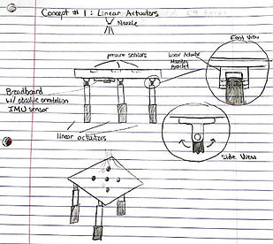
Phase I: Concept 1 Linear Actuators.

Phase I: Concept 3 Actuating Base.

Phase I: Concept 2 Actuating Nozzle.

Stevens Shock Tunnel (cut section of 3-D model).
The eventual concept chosen had to fit within the shock tunnel. Three tentative designs were chosen to be modeled and further analyzed. These 3D models are shown below with a brief description of their merits.
The first concept modeled is shown to the right. This design allows for height adjustment as well as angle adjustment without changing the location of the plate's center. This aspect is crucial in order to avoid changing the positioning of any attached sensors or other equipment. The angles are manually adjusted while the height is remotely adjusted to reduce the number of times the shock tunnel must be reopened. It utilizes a pin to mechanically lock the plate in position, while linear actuators adjust the height.
Pro’s:
-
Consistent, discrete angles
-
Design simplicity
-
Ease of height adjustment
-
IMU sensor not needed
Con's:
-
Angle must be adjusted manually

Phase II: Concept 1 3D Model.
The second concept modeled is shown to the right. This design allows for both height and angle adjustment, but both of these adjustments are made remotely using linear actuators. While this concept has its merits in that the shock tunnel would be opened significantly less often, there is more mass to account for, more budget used for extra actuators, and an issue with the location of the actuators as the angle of the plate increases.
Pro’s:
-
Ease of height/angle adjustment
Con's:
-
Requires additional components
-
Potential loss of consistency/accuracy

Phase II: Concept 2 3D Model.
The third and final concept modeled is shown to the right. This design allows for remote angle variation using a combination of belts and motors to alter the angle of the plate. There is no variation of height for this design, so the entire setup must be moved up and down using a separate assembly or base in order to collect data at different plate heights.
Pro’s:
-
Precision angle movement
-
Remote angle movement
Con's:
-
Angle cannot be easily measured
-
Potential loss of accuracy
-
Height cannot be changed

Phase II: Concept 3 3D Model.